| Aim: To give a schematic representation of separation using gas chromatography Illustration |
ST 18 shows
the schematic make-up of a gas chromatograph.
In gas chromatography the separation takes place in a column. The mobile
phase is a hot gas that flows through the column at a constant rate. The
temperature of the column is adjusted so that all the components in the
sample have a reasonable vapour pressure. In practice this means a column
temperature that is ca. 50°C lower than the boiling point of the components
to be separated. The stationary phase is either a solid or a liquid; we
speak of solid – gas and liquid - gas chromatography respectively.
Liquid – gas chromatography is almost always used; only when inert
gases are being separated is solid - gas chromatography used. The separation
relies on the difference in solubility of the components in the stationary
liquid phase. The one component is more soluble than the other. The most
soluble component stays in the liquid longest and exits from the column
last. The least soluble exits first.
This
technique is used for the separation of substances that are volatile but
that do not decompose at the column temperature. The stationary phase
may, of course, neither vaporise nor thermally decompose at the column
temperature. The maximum temperature that the column can be set at is
around 350°C. The stationary phases that can be usually used at this
temperature are usually polymeric materials, especially polysiloxanes.
In capillary columns the stationary phase consists of a film coated on
the inner wall of the capillary tube. The length of the column varies
from 10 metres to several tens of metres and the diameter varies between
0.5 and 1.0 mm.
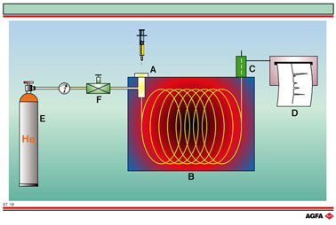
The Illustration
shows the various parts of the gas chromatograph. The components, dissolved
in a volatile solvent, are injected into the injector (A). In the injector
the mixture vaporises and is carried by the carrier gas (usually He or
N2) that is supplied by the gas cylinder (E), via a regulator
(F), to the column (B). This column is situated in a programmable oven
that regulates the temperature. The separation occurs on the column according
to the same principle explained on the previous Illustration, ST 17. The
separated components elute one by one into the detector (C).
One of the most common detection systems is the flame ionisation detector.
In this system the components are burnt in the detector and form ions
which generate a current.
This
current is directly proportional to the concentration of the component
and is recorded on either a recorder or a PC. This produces a so-called
chromatogram. Today, the recorder has mostly been replaced by a PC which
displays the peaks on the screen. The computer program can calculate the
areas under the peaks, which are a measure of the quantity of each component
present in the mixture.